paint-brush
Building a Brushed DC Motor Controller: An Overviewby@andreysolovev
4,138 reads
4,138 reads

Building a Brushed DC Motor Controller: An Overview

by Andrey SolovevMarch 7th, 2021
Read on Terminal Reader
Read this story w/o Javascript
tldt arrow

Too Long; Didn't Read

A DC motor has some advantages, and one of them is the simplicity of its control system. Learn more about its working principles and get some helpful tips.
featured image - Building a Brushed DC Motor Controller: An Overview
Andrey Solovev HackerNoon profile picture

A controller plays an important role in the operation of a DC motor; its importance is even higher for a motor with extended functionality. Simpler motors can do without this device, but we are not going to talk about them in this article.

Here, we’ll take a closer look at a brushed DC (BDC) motor controller, which is a simple and easy-to-build device.

Working Principles of a BDC Motor and its Controller

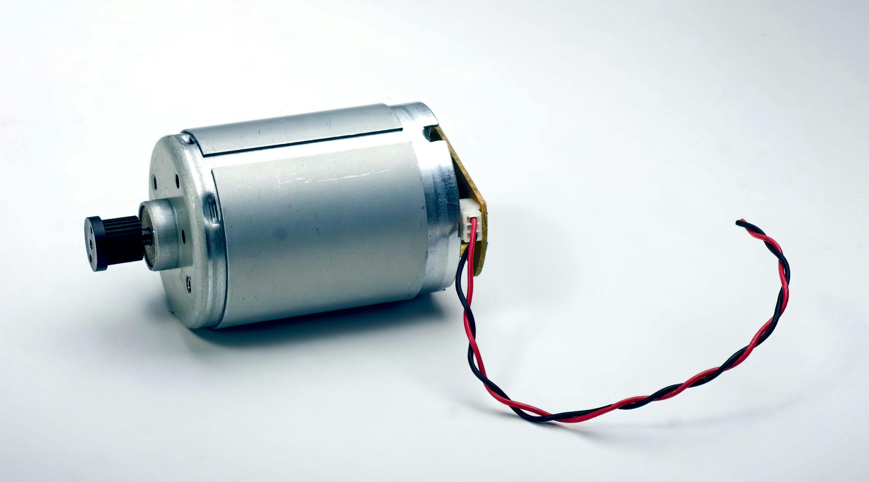
The main components of any DC motor include a moving part - a rotor ( or armature) and a stator, which is always at rest. The stator of a brushed DC motor can have either windings (series, shunt, compound BDC motors) or permanent magnets (permanent magnet BDC motors). The third essential component of a BDC motor is the commutator with brushes that connect the rotor with a DC power supply.

The current flowing through the rotor generates the electromagnetic field around it. As the rotor starts moving, the similar poles of the magnetic fields created around the stator and rotor repel each other and provide a motion. When their opposite poles meet, the commutator switches the current supplied to the rotor. This creates the reverse polarity of the magnetic field, and the motion continues.

A brushed DC motor can use a controller to start and stop the rotation, change its direction, manage the speed and torque. To perform these functions, a BDC motor controller regulates the current and voltage injected into the motor. Brushed DC motors are simple, cost-effective, and easy to control. They can perfectly fit simple low-power applications.

Designing a BDC Motor Controller

To design a BDC motor controller, you can choose an H-bridge, which is a traditional circuit for such types of devices. This electronic circuit has four open / close switches that supply positive and negative voltage by turns. 

By closing high-side and low-side switches in a diagonal pattern, the motor rotates in one direction. The rotational direction will change as soon as these switches are open and the opposite switches are closed.

If you need a motor with a unidirectional rotation, you can build a controller using a simpler circuit with only one open/close switch. Choosing a transistor switch, make sure it meets the required parameters of the motor, for example, the maximum current. Otherwise, the transistor will burn out.

For a low voltage controller, you can opt for power MOSFETs that provide a fast switching speed and high efficiency at a low price. Building a high current BDC motor controller, you can use IGBTs that allow a high level of current and are well suited for complex power electronics systems. 

Another option that you can choose for your project is a GaN transistor that can resist high temperatures and operates at very high frequency and voltage ranges. However, its production cost is still very high, so it will raise the price of your circuit design as well.

You can use either an integrated circuit (IC) or discrete components. From a developer’s point of view, a DC motor controller IC is a simpler and more convenient solution. With a discrete circuit, it will take you the time and effort to assemble and solder the components. 

You have the same options for gate drivers that act as intermediaries between the microcontroller (MCU) and switches. An integrated H-bridge driver is a circuit with built-in power transistors. Despite the simplicity and reliability of its design, the gate driver IC is intended for low-voltage and low-power applications. Additionally, such gate drivers are not interchangeable. If they become discontinued, you’ll have to redesign the schematic together with the printed circuit board.

BDC motor controller circuit design can have various configurations. Building your own device, you should consider the technical requirements and characteristics of the motor.

Let’s briefly go over the design aspects that deserve your attention.

Type of Signal

You can build a digital or analog controller. The main difference between them is that the former comprises MCU-based hardware and firmware. You can combine these two types of signals and design a device that can be controlled with the help of both. 

Type of Power Regulation

A BDC motor controller regulates the speed and torque by changing the power supplied to the motor. You can achieve this by using either a linear or switching voltage regulator. The linear regulator provides stable output voltage and keeps its magnitude constant, irrespective of the input voltage supplied by a power source. 

A switching regulator uses the pulse-width modulation (PWM) method and supplies voltage in pulses, changing its duty cycle (the ratio of the pulse to the pulse period). Thus, you can regulate the speed of the motor by adjusting various duty cycles. A switching regulator has higher efficiency and less power loss. 

Type of Control

Some DC motor controller types can receive feedback from the motors, detect errors, and correct them, bringing the values into line with the setpoints. They are called closed-loop or feedback controllers. Alternatively, an open-loop or non-feedback controller cannot affect the situation, even if a failure occurs, as it will not detect it. You can find such motor controllers in simple systems that don’t need automatic control. 

Motor Characteristics

Depending on the voltage necessary for the motor’s operation, you can choose a low or high voltage controller. A switching regulator works well for controllers with a wide operating voltage range. A linear regulator better suits a low voltage DC motor controller because the excessive input voltage may cause power loss and even thermal overload.

Motor power relies on the current supplied by the power source. Thus, a low-power BDC motor needs a low current controller and vice versa.

Challenges of Building a BDC Motor Controller

Accessibility and easy implementation of BDC motors and their controllers make them a suitable solution for many projects. Despite the simplicity, a brushed DC motor controller design may still involve some challenges. 

For example, the switches in an H-bridge cannot be turned on and off simultaneously. There will always be a moment when all the transistors are open. It may lead to voltage and power loss, or even short-out if the opposite upper and lower switches are turned on.

To avoid this situation, you can introduce dead time, which is the time when all switches of an H-bridge circuit are closed.

PWM frequency (the number of pulse periods per second) is an important parameter that you should adjust in a proper way. Too low or too high PWM frequency will lead to the malfunctioning of the controller and consequently the motor.

Excessive electromagnetic interference caused by the constant switching of a mechanical commutator is a common problem of a brushed DC motor, and you should cope with it too.

Read about BDC motor controller in more detail here.