paint-brush
How to Fix an Ethernet Cable Plug (RJ45 Plug) and Other Ethernet Tipsby@oliverrieder
6,218 reads
6,218 reads

How to Fix an Ethernet Cable Plug (RJ45 Plug) and Other Ethernet Tips

by Oliver RiederOctober 8th, 2021
Read on Terminal Reader
Read this story w/o Javascript
tldt arrow

Too Long; Didn't Read

The locking tab of RJ45 plugs breaks easily and this is one of the most common issues faced by the users of Ethernet cables. An RJ45 plug without a locking tab does not lock properly. This means you can lose your Ethernet connection just when you least need it. There are many situations when a hardwired connection to Ethernet from your iPhone or iPad can be extremely useful. The solution is pretty simple to make this work: Your iOS device; the Ethernet cable; the iPad or iPhone A/C adapter; Apple USB-to-Ethernet adapter;Apple Lightning to USB 3 Camera Adapter or a powered USB hub.

Companies Mentioned

Mention Thumbnail
Mention Thumbnail
featured image - How to Fix an Ethernet Cable Plug (RJ45 Plug) and Other Ethernet Tips
Oliver Rieder HackerNoon profile picture

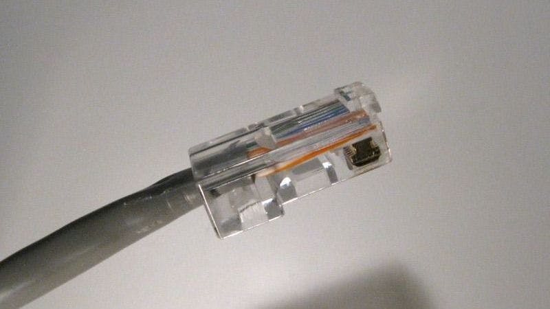
Many of you have probably experienced problems with a broken RJ45 plug. The locking tab of RJ45 plugs breaks easily, and this is one of the most common issues faced by the users of Ethernet cables. Now, I’ll tell you about a temporary solution that will help you make a connection with a broken plug more reliable.

As you know, an RJ45 plug without a locking tab does not lock properly. That means you can lose your Ethernet connection just when you need it the most. Obviously, the best thing to do in this case is to replace the broken plug using an RJ45 crimp tool. Don’t have one? No worries, there’s another way to protect your connection.

1. You’ll need:

A cable tie tool, a sharp knife, cutting pliers, and two small nylon cable ties.

2. Make sure the cable ties are the right size.

It’s important that the head of each cable tie has the proper width to be easily inserted and released from the socket.

Check the width by inserting the head into the socket (it should snap) and pulling it back (there should be some resistance).

I used 4.3 mm wide heads.

3. Cable tie length.

Take one of the cable ties and cut around 4.5 cm (1.8 inches).

4. Then, make its head flat.

You can do this using a sharp knife.

5. Bend the cable tie as shown in the picture below.

6. Take the second cable tie

And use it to tighten the first one.

7. Here’s what you should get:

Now, let’s see what to do next.

8. Tune the position and bends of the first cable tie.

Tune the first cable tie so that it acts as a spring.

9. Done!

Now, the repair plug can be inserted into the Ethernet socket.

Many developers took this into account and decided to improve the jack by wrapping the latch with rubber protection that extends the life of the Ethernet cable.

How to Connect an iPhone or iPad to Wired Ethernet

Well, there are many situations when a hardwired connection to Ethernet from your iPhone or iPad can be extremely useful. For instance, you want to download a large iOS update, but your wireless connection is slow. Or, when Wi-Fi is out, you may need to get online with your iOS device. The cases are many, but the main question is how to do this, considering that iPads and iPhones do not have an Ethernet port.

The solution is pretty simple. Here is what you should gather up in order to make this work:

  1. Your iOS device;
  2. The Ethernet cable;
  3. Apple Lightning to USB cable;
  4. Apple iPad or iPhone A/C adapter;
  5. Apple USB-to-Ethernet adapter;
  6. Apple Lightning to USB 3 Camera Adapter or a powered USB hub.

Now, let’s follow a few simple steps:

  • First, plug the Ethernet-to-USB adapter into the camera adapter, then plug an Ethernet cable into the USB Ethernet adapter. After that, connect the Ethernet cable to your router.
  • Once done, take the lightning cable and connect one of its ends to the camera adapter and the other one to the power adapter (or powered USB hub). Next, plug the power adapter into the wall.
  • Finally, connect the camera adapter to your iDevice. This is it!

It also should be noted that in case you don’t connect the adapter to the power first, you’ll get a notification saying that the connected device cannot be supported.

This is because the Ethernet connection takes much power. More than your iDevice can handle.

Another option to provide Ethernet for MacBook Air (or any other Mac computer) is Apple Thunderbolt Ethernet adapter. The solution allows connecting to a high-performance Gigabit Ethernet network.

You simply plug the device into the Thunderbolt port on your machine and get an RJ-45 port supporting 10/100/1000BASE-T networks.

As for the speed of data transfer, here are the results I got after running some speed tests from my MacBook Pro Retina to a Gigabit-wired Mac Pro:

  • 94 Mbps with Apple USB Ethernet Adapter.
  • 941 Mbps with Thunderbolt to Gigabit Ethernet Adapter.

How to Connect Two Devices to One 8-Wire Ethernet Cable (If You Don’t Have a Hardware Ethernet Splitter at Hand)

Let’s imagine that you have only one 8-wire Ethernet cable to which you need to connect two devices at a time. Can Ethernet cable be split? Sure. I’ll tell you how I do this when I don’t have a special Ethernet port splitter around.

For example, I have one 8-wire Ethernet cable running to the room where there is one Ethernet outlet. The other end of the cable goes to the server room, where it’s punched down into the patch panel.

I have no time to run the second cable. And I remember that in a 5e cable (a standard twisted-pair cable consisting of 4 pairs) only two pairs are used for data transmission at speeds up to 100 Mbps, unless the device uses PoE - switchboard power. So, to solve this problem, I take:

  • a piece of a Cat5e Ethernet cable, approximately 50 cm;
  • two connectors;
  • four Ethernet sockets (I need only modules) or two double sockets;
  • a crimp tool and a punch-down tool (if you lack the latter one you can do it with a flat screwdriver).

First, I divide the piece of the cable into two parts, each about 25 cm. Then, I crimp each of them on one end.

Next, I divide the second end into two parts, the pairs I choose are white-orange/orange + white-green/green, and, respectively, white-brown/brown + white-blue/blue. Then punch down the wires into the sockets using the “b” - scheme. Now, I get one socket with white-orange/orange + white-green/green pairs. And the other one with white-brown/brown and white-blue/blue pairs.

Now, I do the same to the second part of the cable. Once done, I can connect the cable to devices according to the scheme: two patch cords run from two ports of a switch. I plug the patch cords into the “handmade” sockets, and then I plug the free end of the cable with the connector into the patch panel. Now, let’s go to the room and do the same thing.

Voila! Two devices work over the same cable. What’s nice is that it takes no more than 20 minutes.

How to Monitor Ethernet Connections Using a Passive Network Tap

A passive Ethernet tap is a simple cross of CAT5 cables spliced together to allow Ethernet users to monitor in-line Ethernet communications. This unpowered device can only capture 10BASE-T and 100BASE-TX, and each of its sniffing connectors can monitor only the traffic transmitted one way.

In order to use a tap within your Ethernet network, you need to insert it in-line on the required Ethernet connection (for instance, between a PC and a switch) and run a dedicated analyzing tool, e.g., Wireshark, on the machine linked to one (or both) of the sniffing connectors. The monitoring ports can only capture the transported data, so you don’t have to worry that any traffic can be transmitted onto the wire from your monitoring station.

To sniff traffic in both ways, you have to use two taps. By using two taps, you get the ability to monitor the inbound data passed through one tap and outbound data passed through the other tap. At the same time, the practice shows that monitoring just one direction at a time is enough for efficient troubleshooting of Ethernet issues.

How to modify your Ethernet cable

If you have a bit of the experience of making network cables like a crossover or straight one, I think the following Ethernet cable hacks will be of interest to you. Based on the original layout of the standard Ethernet cable, I’ll tell you what you can achieve using the same wire.

To make cable modifications, you’ll need a CAT5/CAT5e networking cable, a few RJ45 connectors, a few RJ11 connectors, and a crimp tool.


Before we start, please note that we’ll be using the four wires which are usually useless in a standard 8-wire cable and don’t serve for network communications. These are 1, 2, 3, and 6, getting TX+, TX-, RX+, and RX- respectively. See below:

Also, remember which color you are using on one end of the cable, as you'll have to utilize the same on the other end.

Scenario 1. Twin

Let’s say you want to connect your PS3 and Xbox 360 but the router is too far and you don't have enough room for another cable. The solution? Twin straight cables made from a single one. Just use four wires for each connector and remember your color code.

For one device:

CONNECTOR 1

Wire color - PIN no.

  • Blue - 1
  • Blue White - 2
  • Green - 3
  • Green white - 6

CONNECTOR 2

Wire color - PIN no.

  • Blue - 1
  • Blue white - 2
  • Green - 3
  • Green white - 6

For the other one:

CONNECTOR 3

Wire color - PIN no.

  • Brown - 1
  • Brown White - 2
  • Orange - 3
  • Orange white - 6

CONNECTOR 4

Wire color - PIN no.

  • Brown - 1
  • Brown White - 2
  • Orange - 3
  • Orange White - 6

Scenario 2: network + phone cable.

About Phone connectors. RJ11, RJ14, and RJ25 are interface standards that allow connections for one, two, or three telephone lines using the same six-position modular connector. The main difference between them is that they use a different number of contacts (two, four, and six, respectively).

If you only need to have a phone and LAN cable, you can use RJ25, and if you need LAN, power, and phone, use RJ11.

Now, let’s see how to create an all-in-one phone and Ethernet cable by adding an RJ14 connector.

CONNECTOR 3 - RJ14

Wire color - PIN no.

  • Brown - 1
  • Brown White - 2
  • Orange - 3
  • Orange white - 4

CONNECTOR 4 - RJ14

Wire color - Pin no.

  • Brown - 1
  • Brown White - 2
  • Orange - 3
  • Orange White - 6

Scenario 3: Network + Phone cable + Power supply.

Note that RJ11 uses only middle 2 pins (2 and 3) and not 1 and 4.

CONNECTOR 3 - RJ11

Wire color - PIN no.

  • Brown - 2
  • Brown White - 3

CONNECTOR 4 - RJ11

Wire color - Pin no.

  • Brown - 2
  • Brown White - 3

and the rest of the two wires will be for power:

Wire color - Power wire color

  • Orange - Red
  • Orange/white -Black

Wire color - Power connector wire

  • Orange - Red
  • Orange/White - Black