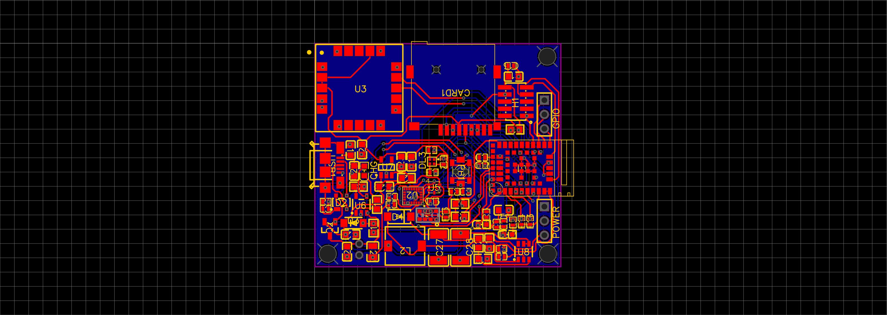
Combining 3 Arduino boards to create a GPS tracker & data logger. I had an idea to combine the new Arduino Nano 33 BLE Sense with an SD card and GPS module for a side project that logs GPS and IMU data. I decided to purchase the , the , and the and connect them all together. Unbeknownst to me at the time, these boards aren’t footprint-compatible, so I combined them with a breadboard 😐. Nano 33 MKR Mem Shield MKR GPS Shield It took a little while to get all the libraries installed and everything connected appropriately. The biggest challenge was the GPS module. It really helps to start debugging the GPS’ example code outside; where satellite signal is available 😉. Prototype Code The full Arduino sketch for the above connected system . But, might as well have a quick overview of the code. Throwing the imports and definitions below: is here dataFile; chipSelect = ; SFE_UBLOX_GPS myGPS; latitude = ; longitude = ; speed = ; satellites = ; timeout = ; lastGPSTime = ; ax, ay, az; gx, gy, gz; DEBUG = true; counter = ; # include <SparkFun_Ublox_Arduino_Library.h> # include <Arduino_LSM9DS1.h> # include <Arduino_APDS9960.h> # include <SPI.h> # include <SD.h> // SD Vars File int 4 // GPS Vars // Connected via UART long 0 long 0 long 0 byte 0 int 50 long 0 // IMU Vars float float // Misc bool int 0 # LEDR (22u) define # LEDG (23u) define # LEDB (24u) define Next, we need to do all the GPS and SD card setup. The tricky part here was making sure to remove the DATALOG.csv file every time we start up. () { . ( ); (! ); Serial1. ( ); (!Serial1); ( , ); (LEDR, ); (LEDB, ); (LEDG, ); (LEDR, ); (LEDG, ); (LEDB, ); (!myGPS. (Serial1)) { . (F( )); ( ); } . ( ); (! . (chipSelect)) { . ( ); ( ); } ( . ( )) { . ( ); dataFile = . ( , FILE_WRITE); dataFile. (); } ( ); dataFile = . ( , FILE_WRITE); dataFile. ( ); . ( ); (!APDS. ()) { . ( ); } APDS.setGestureSensitivity( ); . ( ); (!IMU. ()) { . ( ); ( ); } . ( ); } void setup // Setup User Terminal Serial begin 115200 // UART to PC/Mac while Serial begin 9600 // UART to GPS while // Initialize digital pin LED_BUILTIN as an output. pinMode LED_BUILTIN OUTPUT pinMode OUTPUT pinMode OUTPUT pinMode OUTPUT digitalWrite HIGH // LOW triggered LED.... digitalWrite HIGH digitalWrite HIGH // Setup GPS if begin Serial println "GPS not detected!" while 1 Serial println "GPS Started!" // Setup SD Card if SD begin Serial println "SD Card failed or not present!" while 1 // Remove Existing DATALOG.CSV file if SD exists "DATALOG.CSV" SD remove "DATALOG.CSV" SD open "DATALOG.CSV" close delay 500 // Make sure existing DATALOG.CSV file is gone // Create new CSV file with appropriate headers SD open "DATALOG.CSV" println "Count,AccX,AccY,AccZ,GyrX,GyrY,GyrZ,Lat,Long,Speed" // Done with SD Card Init Serial println "SD Card Initialized!" // Setup Gesture Sensor if begin Serial println "Error initializing gesture sensor!" 85 Serial println "Gesture sensor initialized!" // Setup IMU if begin Serial println "Failed to initialize IMU!" while 1 Serial println "IMU initialized!" Now we can log all of the data to the SD Card. Note that we could use the Gesture sensor to stop and start recording (in the main loop). () { ( () - lastGPSTime > ) { lastGPSTime = (); latitude = myGPS.getLatitude(timeout); longitude = myGPS.getLongitude(timeout); speed = myGPS.getGroundSpeed(timeout); satellites = myGPS.getSIV(timeout); (DEBUG) { . (F( )); . (latitude); . (F( )); . (longitude); . (F( )); . (F( )); . (speed); . (F( )); . (F( )); . (satellites); } } (IMU.accelerationAvailable()) { IMU.readAcceleration(ax, ay, az); (DEBUG) { . (F( )); . (ax); . (F( )); . (ay); . (F( )); . (az); } } (IMU.gyroscopeAvailable()) { IMU.readGyroscope(gx, gy, gz); (DEBUG) { . (F( )); . (gx); . (F( )); . (gy); . (F( )); . (gz); } } (APDS.gestureAvailable()) { (APDS.readGesture()) { GESTURE_UP: . ( ); ; GESTURE_DOWN: . ( ); ; GESTURE_LEFT: . ( ); ; GESTURE_RIGHT: . ( ); ; : ; } } (dataFile) { counter += ; dataString = ; dataString += (counter) + ; dataString += (ax) + ; dataString += (ay) + ; dataString += (az) + ; dataString += (gx) + ; dataString += (gy) + ; dataString += (gz) + ; dataString += (latitude) + ; dataString += (longitude) + ; dataString += (speed); dataFile. (dataString); } ( ); } void loop if millis 500 millis // Update the timer if Serial print "Lat: " Serial print Serial print " Long: " Serial print Serial print " (degrees * 10^-7)" Serial print " Speed: " Serial print Serial print " (mm/s)" Serial print " satellites: " Serial println if if Serial print "Accel x: " Serial print Serial print " y: " Serial print Serial print " z: " Serial println if if Serial print "Gyro x: " Serial print Serial print " y: " Serial print Serial print " z: " Serial println if // A gesture was detected, read and print to serial monitor switch case Serial println "Detected UP gesture" break case Serial println "Detected DOWN gesture" break case Serial println "Detected LEFT gesture" break case Serial println "Detected RIGHT gesture" break default // ignore break if 1 String "" String "," String "," String "," String "," String "," String "," String "," String "," String "," String println delay 150 // Don't pound too hard So this is all fine and good. Prototype concept has been vetted! Time to build a custom PCB with the same functionality. PCB Design PCB design was definitely an experience, with a decent learning curve. I used . My first step was obtaining the schematics from the Nano 33, the MKR Mem Shield and the MKR GPS Shield. These were easy enough to find in the tech links and via Github. As they are Eagle schematic files, I downloaded the Eagle trial version to analyze in depth. easyeda to build my custom PCB I basically copied the whole Nano 33 BLE schematic as is, including matching up the component names and numbers. I then added the GPS module (top center) and had to think about how to program via J-Link (top right): Hoping for the best, I went ahead and sent off the design to to be built and assembled. It was a decently smooth process, with some questions about a part name and orientation. PCBWay After a couple of weeks I got the plain PCB boards in the mail: And a few more weeks later (6 weeks) I got the fully assembled PCB boards back! Flashing the Arduino bootloader I bought the to be able to program the custom board. I also installed all the J-Link drivers, etc. . J-Link EDU Mini cable A similar tutorial can be found here You can find the Arduino binary file here: bootloader.bin <username> Arduino15 arduino bed bootloaders bootloader.bin /Users/ /Library/ /packages/ /hardware/m /1.1.4/ /nano33ble/ I ended up flashing the bootloader via . Fingers crossed everything would work🤞. nRF Connect And it did! An Arduino Nano would pop up and connect to my MacBook when I plugged in the USB cable. Turns out I had made a few mistakes in my though reverse engineering, . The Nano 33 schematic has a Do Not Populate (DNP) for a pull up resistor on the RESET pin. I should have added test points for this resistor as well. I ended up hand-soldering a 4.7K. This stopped my board from auto-resetting every second (could also adjust the UICR to disable the RESET pin).The schematic shows a 1M Ohm resistor connecting the USB shield to ground. But the Eagle file shows 330 Ohm — should be 330 Ohms. There is tons of debate and trade-offs here.I messed up a wire with the gesture sensor, so that didn’t work. However it still measured RGB colors. I ended up fixing these issues. To make this device portable, I added a battery connection and LiPo charging, as well as load sharing. I also added a 5V and 3.3V power rail to power external devices. Having learned from more research, I decided to add more decoupling capacitors and various connectors (including GPIO). I sent the new design with a more compact PCB layout to PCBWay! Currently waiting on those boards to get back 😎.