paint-brush
9 Steps To Create A Motion Control Project In TIA Portal With Sinamics S120 by@karthik-muthineni
5,514 reads
5,514 reads

9 Steps To Create A Motion Control Project In TIA Portal With Sinamics S120

by Karthik MuthineniApril 18th, 2021
Read on Terminal Reader
Read this story w/o Javascript
tldt arrow

Too Long; Didn't Read

This blog discusses about controlling Sinamics S120 drive motion using Simatic S7–1500 and TIA Portal software. In our example, a drive unit is to be assembled for a motor. The Control Unit must be connected to S7-1500 via PROFINET (Figure a) The control unit must be configured using STARTER software. The PLC should be configured as MAS, which gives the drive components the control role to “master” The drive components are wired by means of Drive–Cliq.

Companies Mentioned

Mention Thumbnail
Mention Thumbnail

Coins Mentioned

Mention Thumbnail
Mention Thumbnail
featured image - 9 Steps To Create A Motion Control Project In TIA Portal With Sinamics S120
Karthik Muthineni HackerNoon profile picture

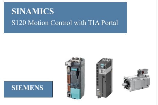
This blog discusses about controlling Sinamics S120 drive motion using Simatic S7–1500 and TIA Portal software. In our example, a drive unit is to be assembled for a motor. The following components are required for the drive unit:

  1. Control Unit CU 310–2PN
  2. Power Module PM 240–2
  3. Synchronous Servo Motor of 1FK7 family
  4. Motion-Connect Drive-Cliq Cable
  5. Motion-Connect Power Cable
  6. Memory Cards
  7. Simatic S7–1500

The following prerequisites must be fulfilled before you start:

  1. The CompactFlash Cards with firmware must be inserted into S7–1500 and CU 310–2PN.
  2. The drive components are wired by means of Drive–Cliq.
  3. The Control Unit must be connected to S7–1500 via PROFINET (Figure a).
  4. The PROFINET interface of S7–1500 is connected to a PC through PROFINET cable.
  5. The Control Unit must be configured using STARTER software.
  6. The TIA Portal V15.1 software must be installed on your PC.


For software installation procedure, refer to SinamicsSoftware.

For hardware wiring of S120 components, refer to SinamicsHardware.

For configuring Control Unit using STARTER, refer to SinamicsStarter.

Creating project in TIA Portal

To create the project in TIA Portal, carry out the following steps:

Step 1: Creating project

Open TIA portal V15.1 and create new project by specifying name and click “Create” as shown in Figure1.

Next, click on “Project view” located at bottom of the window.

Step 2: Adding devices to the project

In the project navigator (left side), click “Add new device”. From the dialog window select S7–1500 CPU with order number 6ES7 512–1CK01–0AB0 as shown in Figure 2.

Open Hardware Catalog (on right side), click “other field devices” and select the S120 CU 310–2PN version 4.8 Control Unit from the dropdown list as shown in Figure 3.

The Control Unit should be added to the Network view. Assign Profinet interface of Control Unit to PLC by clicking on “Not assigned” and selecting the PLC_1 Profinet Interface_1 as shown in Figure 4.

Open the Topology view and connect Port 2 of PLC to the Port 1 of Sinamics S120 (This assigning should be made according to the way you have connected physically) as shown in Figure 5.

Step 3: Assigning IP Addresses

Open the PLC in the Device view and navigate to Properties > General > Ethernet addresses. Assign IP address to PLC as shown in Figure 6. And navigate to “System and clock memory” to select “Enable the use of system memory byte” and “Enable the use of clock memory byte” checkboxes.

In the same way, assign IP address to the Sinamics S120 as shown in Figure 7.

You need to select the type of telegram associated with the Sinamics drive. To do so, double click on the Sinamics S120 in Device view. In the Hardware catalog, click “Module” to open the drop-down. Double click on “DO Servo”, a “submodules” folder should appear. Click on it to open drop-down list. Drag and drop “SIEMENS telegram 105” to the “Module area” on the left side as shown in Figure 8.

Step 4: Real time settings

The PLC should be configured as MASTER, which gives commands to the drive components. To do so, open the PLC in Device view and go to real-time settings. Change the Synchronization role to “Sync master” as shown in Figure 9.

Open the Sinamics S120 in Device view and navigate to Advanced options. Scroll down and select the “Isochronous mode” checkbox as shown in Figure 10. This helps the Sinamics S120 to sync its clock with the clock of PLC.

Go to Real time settings of Sinamics S120 and change RT class to “IRT” as shown in Figure 11.

Step 5: Adding Technology objects

In the Project tree, navigate to “Technology objects” and click “Add new object” as shown in Figure 12.

A new dialog opens, select the “TO_PositioningAxis” and give a name to it as shown in Figure 13.

Next. click on “Hardware interface” and select the PROFINET interface for your Servo from the drop-down list as shown in Figure 14.

Do the following as shown in Figure 15.

Step 6: Adding Program blocks

In the Project tree, navigate to Program blocks and click “Add new block” and give a name to it as shown in Figure 16.

In the “Instructions” (on right side), go to Technology > Motion Control (1) and select “MC_Power” and “MC_Moverelative” (Drag & Drop to ladder). Click on “Technology objects” (2), drag and drop “MotionControl_Position” (3) to the “Axis” of MC_Power (4) and “Moverelative” (5) as shown in Figure 17. (Select “Multi-Instance” for all the blocks)

Assign Power tag to “Enable” of MC_Power block. Right click on Power tag and define it as shown in Figure 18.

In the same way define tag “execute” for MC_Moverelative block and give values for “Distance” and “Velocity” as 1000 mm and 500 mm/s as shown in Figure 19.

Similarly, define “done1” of MC_Moverelative as shown in Figure 20.

Next, drag and drop “MC_Halt” from Motion control folder. and assign tags as shown in Figure 21.

Next, drag and drop “TON” from Timer operations folder. Assign the time delay as 5000 ms (T#55), define tag “Timer1”, as shown in Figure 22.

Next drag and drop another “MC_Moverelative” and assign values as shown in Figure 23.

Add another new program block and name it as “MC_Code” as shown in Figure 24.

Create tag “Start power” as shown in Figure 25.

Create the following network shown in Figure 26.

Open Main [OB1], drag and drop “MC_Code” and “MC_Block” to the ladder network as shown in Figure 27.

Step 7: Save and download

Save the project and download to S7–1500 as shown in Figure 28.

Step 8: Go ONLINE

Press “Go online” (1), go to “MC_Code” (2), click “Monitor on/off” (3), right click on “Start power” modify to 1 (4), and right click on “start execute” modify to 1 (5) as shown in Figure 29.

Your motor starts rotating!!!

Step 9: Trace

Trace function is used to track or record the input or output at the required condition. To do so, navigate to “Traces” in project tree and add new trace as shown in Figure 30.

Next, select the signals that you want to record by clicking on the drop-down button as shown in Figure 31.

Switch to Diagram tab (1), download the trace configuration onto device (2), and click Activate recording (3) to plot the graph as shown in Figure 32.

BONUS

Just download the setup file (.ap15_1) to your device and repeat Step 8. (GITHUB)

Tip #1

If Simatic S7–1500 switches to “STOP” mode frequently, this could be due to communication overload on S7–1500. This can be solved by decreasing the load on cpu. To do so, open S7–1500 in device view and navigate to Properties > General > Communication load. Change “cycle load due to communication” to the lowest value (15%) as shown in Figure 33.

Also published at https://karthikm618.medium.com/sinamics-s120-motion-control-using-s7-1500-and-tia-portal-734522f4b9f2