A Clock Collector

Nov 28, 2023
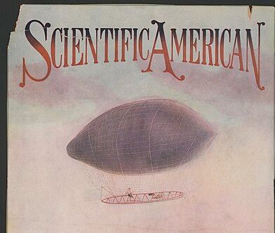
Oldest US science mag (est. 1845). Features contributions from Einstein & Nobel laureates. Public domain only (fansite)
Oldest US science mag (est. 1845). Features contributions from Einstein & Nobel laureates. Public domain only (fansite)
Oldest US science mag (est. 1845). Features contributions from Einstein & Nobel laureates. Public domain only (fansite)
Oldest US science mag (est. 1845). Features contributions from Einstein & Nobel laureates. Public domain only (fansite)

Nov 28, 2023
Nov 28, 2023