227 reads
Section II.—The Contemporaries of James Watt
by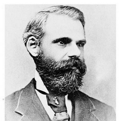 byRobert Henry Thurston@roberthenrythurston
Robert Henry Thurston was an American engineer, and Professor of Mechanical Engineering
April 16th, 2023


Robert Henry Thurston was an American engineer, and Professor of Mechanical Engineering


Robert Henry Thurston was an American engineer, and Professor of Mechanical Engineering
About Author

Robert Henry Thurston was an American engineer, and Professor of Mechanical Engineering
Comments