Authors:
(1) Hamed Alimohammadzadeh, University of Southern California, Los Angeles, USA;
(2) Rohit Bernard, University of Southern California, Los Angeles, USA;
(3) Yang Chen, University of Southern California, Los Angeles, USA;
(4) Trung Phan, University of Southern California, Los Angeles, USA;
(5) Prashant Singh, University of Southern California, Los Angeles, USA;
(6) Shuqin Zhu, University of Southern California, Los Angeles, USA;
(7) Heather Culbertson, University of Southern California, Los Angeles, USA;
(8) Shahram Ghandeharizadeh, University of Southern California, Los Angeles, USA.
Conclusions and Current Efforts, Acknowledgments, and References
FLSs will facilitate both kinesthetic (force) and tactile (skin-based) feedback to a user. While the former provides the shape and hardness of a virtual object, the latter renders an object’s surface properties. Both motivate the disaggregated FLS architecture of Figure 4 with diverse plug-in devices. To illustrate, textures for different surfaces may be rendered using different vibration actuators [19]. An actuator may be a plug-in device to the FLS system bus, enabling an experimenter to evaluate the actuator and its tactile feedback.
An FLS acts as an encountered-type haptic device. Traditional kinesthetic feedback haptic rendering uses a vector-field approach [41] where the force to be displayed to the user is calculated based on their position in the 3D environment and geometric models of the virtual objects. Our FLS-based system will take a similar approach and calculate the desired force based on the user’s position and the 3D model of the object(s) to be rendered. For example, in displaying a virtual wall, the user is free to move their hand around the environment until their position penetrates inside the virtual wall, at which time the FLS would make contact with their hand to apply a force and prevent them from penetrating further into the virtual wall (Fig. 5). Using measurements of the FLS’s position and a 3D model of an object, we can determine how far the user has penetrated into the virtual object to calculate the amount of force to display to the user.
With grounded impedance force-feedback haptic devices, the calculated force is then converted to motor torque using the device’s calibrated Jacobian matrix so that the desired force can be displayed to the user. Since the controllable output of the drones is thrust, displaying a set force to the user requires careful calibration between the commanded thrust and the resulting force. Previous researchers have completed this calibration for single axes of thrust/force for the Parrot AR.Drone [1]. Displaying more complex objects and interactions in 3-dimensions requires a more complete calibration of the system.
Force Amplification: The size of the FLS plays an important role in its dynamics and the force that can be displayed to the user. The FLS’s motors determine the highest RPM that can be generated, and the propellers’ ratio of pitch:diameter affects the force per RPM generated from the air pushing downwards. A larger FLS usually means larger diameter propellers, leading to higher forces at a given RPM. However, the force that we will be able to output with an FLS will be significantly less than that of a traditional kinesthetic haptic device; for example, the common 3D Systems Touch device has a maximum force output of 3.3 N. The modality of human sensing also varies based on the level of force provided, with small forces (<1 N) being sensed as tactile information through the skin rather than kinesthetic information through the muscles [34].
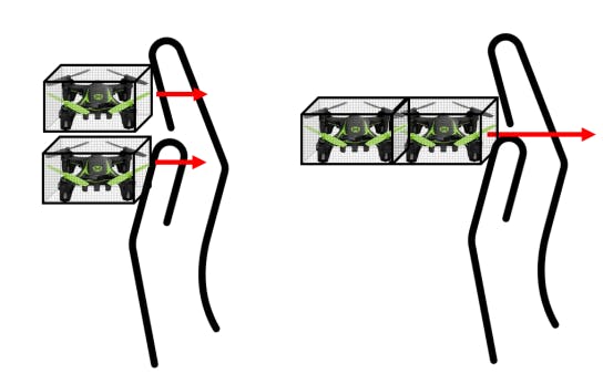
Therefore, a single FLS will not be capable of providing sufficient force for a salient haptic interaction, especially if we want to generate the kinesthetic sensations necessary for displaying a rigid object. Therefore, the FLSs must coordinate together to combine their thrust so that an amplified force can be applied to the user. This coordination must be done in such a way that the formation remains stable during flight and that force can be passed between drones before eventually being felt by the user. This force amplification can be done either by FLSs in a parallel or series configuration (Fig. 6). In parallel, multiple FLSs will contact the user at the same time and will each provide a force proportional to that FLS’s disturbance from its own set-point. In series, only a single FLS will be in contact with the user, and both FLSs will have the same disturbance from their set-point; the user feels their combined force.
User Safety: The goal of our system is to provide non-constrained encountered-type haptic feedback directly to users. To do this, the FLS must (1) be modified to allow users to safely have direct contact and (2) react to the user’s gesture input (e.g. push the FLS away from its desired position), and (3) provide meaningful haptic feedback. With the first, we use a cage to separate the user’s hand from the rotors. Cage shape, weight, and spatial density are key considerations that effect safety, lighting, and flying capability of the FLS. The added weight of the cage would affect the drone’s dynamics and induce imbalance issues when not calibrated. Spatial density of the cage’s mesh is important to prevent the user’s finger from accidentally penetrating the surfaces while not affecting the aerodynamics and lighting of the drone too significantly. However, too fine of a spatial density may significantly affect both the lighting and the flying ability of the drone. A balance must be made between choosing a mesh fine enough to protect the user’s fingers, but coarse enough to not disrupt the airflow and provide the desired textured lighting.
Sensing Users: To create an effective touch-based interaction, each FLS should be capable of sensing touch from the user. At a minimum, the FLS should be able to detect the presence or absence of touch, and preferably it will be able to detect the location of touch as well. Capacitive sensors could be integrated into the FLS cage to easily detect the presence of user contact, and a more complex capacitive skin could be developed to determine point of contact. However, determining force of contact from this type of sensor would be challenging, and if this information is required more a more complex mesh of sensors must be developed. Here we propose to use open-loop control for the forces, so direct force sensing from the user is not required.
This paper is available on arxiv under CC 4.0 license.