paint-brush
How Zero-Knowledge Proofs and Rank-1 Constraint Systems Transform Blockchain Scalabilityby@escholar
329 reads
329 reads

How Zero-Knowledge Proofs and Rank-1 Constraint Systems Transform Blockchain Scalability

tldt arrow

Too Long; Didn't Read

Zero-knowledge proofs (ZKPs) and Rank-1 Constraint Systems (R1CS) are reshaping blockchain scalability by introducing innovative cryptographic solutions. Learn how these advancements are overcoming scalability challenges and fostering growth in decentralized finance (DeFi) and blockchain networks.

People Mentioned

Mention Thumbnail
featured image - How Zero-Knowledge Proofs and Rank-1 Constraint Systems Transform Blockchain Scalability
EScholar: Electronic Academic Papers for Scholars HackerNoon profile picture

Authors:

(1) Chenhao Shi, Shanghai Jiao Tong University;

(2) Ruibang Liu, Shanghai Jiao Tong University;

(3) Guoqiang Li†, Shanghai Jiao Tong University.

Table of Links

Abstract & Introduction

Preliminaries

Normalization Algorithm

Evaluation

Conclusion & References

II. PRELIMINARIES

This section introduces the basic concepts and principles of zero-knowledge proof and discusses the role of R1CS and Circom in zero-knowledge-proof systems. It also explores the limitations of existing normalization techniques for R1CS and presents the proposed data-flow-based normalization generation algorithm, which is motivated by these limitations.


A. ZK-SNARKS


Zk-SNARK, which stands for Zero-Knowledge Succinct Non-interactive Argument of Knowledge, is a type of zeroknowledge proof introduced in a 2014 paper [12]. The objective of zk-SNARK is to enable one party to prove to another that they possess specific knowledge without revealing the knowledge itself, and to do so concisely and efficiently. The working principle of Zk-SNARK can be simplified into several steps. First, users convert the information they wish to verify into a mathematical problem called a computation. This computation can be implemented using any high-level programming language, such as OCaml, C++, Rust, or hardware description languages like Circom.


Fig. 1. The pipeline diagram for zk-SNARKS.


Next, the computation result is usually transformed into an arithmetic circuit, a computational model for computing polynomials. An arithmetic circuit consists of inputs and multiple gates, performing an essential arithmetic operation such as addition or multiplication. The entire arithmetic circuit can be used to generate a specific format (R1CS), which takes the form of a constraint-based formula system (rank-1 constraint system) expressing the constraints of the arithmetic circuit. A verifiable arithmetic circuit is one of the inputs of the zk-SNARKs algorithm.


The Quadratic Arithmetic Program (QAP) is a variant of linear pcp and plays a crucial role in the verifiable arithmetic circuit’s conversion into the QAP format. QAP is a formula system that employs polynomials to represent the behavior of the arithmetic circuit. By utilizing QAP, the security of the zkSNARKs algorithm is enhanced, along with the improvement of its implementation efficiency [13].


Finally, there is the zk-SNARK stage, where the verifiable arithmetic circuit and QAP are used to generate a proof. ZkSNARKs are powerful privacy protection protocols that can be utilized in digital payments, blockchain technology, and other fields. They can verify the authenticity of information while protecting the user’s privacy. Despite its relatively complex working principle, zk-SNARK technology has found widespread application, bringing higher security and privacy protection to the digital world.


B. Circuit Language


ZKP technology can address several fundamental issues in the modern digital world, including identity user’s verification without compromising their private information and safeguarding privacy data from unauthorized exploitation. Within ZKP, arithmetic circuits play a vital role in describing and computing complex operations. These circuits consist of a series of logic gates that can perform various arithmetic operations, such as addition, multiplication, and division. By combining these basic operations, the complex arithmetic circuits can be constructed to execute diverse computational tasks.


The circuit referred to here is a theoretical computational model, not an actual electronic circuit.


This is the formal arithmetic circuit definition in theoretical computer science [14].


**Definition II.**1. A finite field field F is a field that contains a finite number of integer elements.


F = {0, . . . , p − 1} for some prime p > 2


The operations +, ×, = on F should (mod p) after calculation.


Definition II.2. A circuit is a triple (M, L, G), where


· M is a set of values,


· L is a set of gate labels, each of which is a function from Mi to M for some non-negative integer i (where i represents the number of inputs to the gate), and


· G is a labelled directed acyclic graph with labels from L.


Definition II.3. A arithmetic circuit is a map C : F n → F, where F is a finite field.


  1. It is a directed acyclic graph (DAG) where internal nodes are labeled +, −, or × and inputs are labeled 1, x1, . . . , xn, the edges are wires or connections.


2) It defines an n-variable polynomial with an evaluation recipe.


3) Where |C| = # gates in C.


This chapter mainly focuses on the Circom language, employed at the core step of zk-SNARK protocols for describing arithmetic circuits. Within the framework of ZKP systems, several commonly used arithmetic circuit description languages exist, including Arithmetica, libsnark DSL, and Circom. These languages are typically employed for building and verifying ZKP systems and can be used to describe various arithmetic circuits, such as linear constraint systems (LCS), bilinear pairings, and quadratic circuits.


By representing an arithmetic circuit as a constraint system, Circom’s core idea involves describing inputs, outputs, and computation processes as linear equations and inequalities. This approach allows developers to define complex computation processes and generate the corresponding R1CS constraint system. Circom provides a set of high-level abstract concepts, enabling developers to focus more on the algorithm without being overwhelmed by low-level implementation details.


C. Rank-1 Constraint Systems (R1CS)


R1CS, a common Arithmetic Circuit format that underlies real-world systems [2] and an important part of the zkSNARKS algorithm groth16[15], represents computations as a set of constraint conditions, namely linear equations and inequalities. Each equation has its own set of coefficients, while each variable represents an input or output value. These equations and inequalities describe the limiting conditions of the computation, implying that satisfying these conditions correctly calculates the corresponding output result for the given input sequence. R1CS includes a formal definition of constraint-based computation rules, which can be verified using a set of public parameters and a private input sequence. For a more detailed understanding of the formal definition of R1CS, refer to Vitalik’s blog [13].


Definition II.4. R1CS is a format for ZKP ACs. An R1CS is a conjunction of constraints, each of the form:


For example, a satisfied R1CS is shown in Fig.2:


Fig. 2. A satisfied R1CS.


This constitutes a first-order constraint corresponding to a circuit multiplication gate. If we combine all constraints, we obtain a first-order constraint system.


R1CS is widely used in practical applications as a powerful computational model. It serves as an integral component of the groth16 algorithm, which is a popular version of zk-SNARK algorithms. R1CS plays a crucial role in improving developers’ understanding of computer science and cryptography. Additionally, it offers crucial support for various privacy protection measures.54


In this paper, we propose the R1CS paradigm for constraint groups. It imposes constraints on the form and ordering of variable constraints.


Definition II.5. R1CS paradigm is an R1CS satisfies the following requirements:


  1. If a constraint in the R1CS paradigm contains multiplication between variables, it cannot have any other operators.


2) If a constraint in the R1CS paradigm does not contain multiplication between variables, it cannot contain intermediate variables generated by other linear constraints.


3) The ordering of constraints and variables (defined in Definition II.4) in the R1CS paradigm must be consistent with the ordering method (× is in front of +) in this paper.


The specific adjustments required for converting a general constraint system into an R1CS paradigm will be explained through examples with concrete constraints.


Requirement 1 suggests that complex quadratic constraints in the R1CS should be split into simpler forms.


For instance.


a × b + c + d = f =⇒ a × b = r, r + c + d = f


5 × a × b = c =⇒ 5 × a = r, r × b = c


Requirement 2 indicates that linear constraints in the R1CS system must be eliminated by removing intermediate variables defined by other linear constraints. For example,


a + b = c, c + d = e =⇒ a + b + d = e


The specific sorting methods in requirement three will be discussed in later sections outlining the algorithm’s steps.


D. Data Flow Graph


In a bipartite-directed graph, known as a data flow graph, there are two types of nodes: links and actors. Actors are utilized to represent various operations, while links serve as the means by which data is received by actors. Additionally, arcs allow links to transmit values to actors. The formal definition of this concept can be found in Dennis’ paper [16].


Definition II.6. A data flow graph is a bipartite labeled graph where the two types of nodes are called actors and links.


G = ⟨A ∪ L, E⟩ (1)


where


A more detailed description can be found in [17].


E. Weighted Pagerank Algorithm


In this paper, we adopt the weighted PageRank algorithm to compute the weight of each node in the data flow graph [18].


Pagerank algorithm is a method used for computing the ranking of web pages in search engine results. It was initially proposed by Larry Page and Sergey Brin, co-founders of Google, in 1998 and has since become one of the most essential algorithms in the field of search engines.[19]


The algorithm assesses online web pages to determine their weight values, which it then utilizes to rank search results. PageRank is based on the notion that the weight of a web page is influenced by both the quantity and quality of the other web pages that link to it.


The main steps of the Pagerank algorithm are as follows:


  1. Building the graph structure: First, the web pages and links on the internet must be converted into a graph structure. In this structure, each web page corresponds to a node and each link to a directed edge that points to the linked web page.


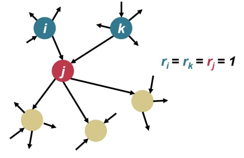
2) Computing the initial scores of each page: In Pagerank, the initial score of each page is set to 1. This means that initially, each node has an equal score.


Fig. 3. The initial state of Pagerank algorithm.


3) Iteratively computing the scores of each page: Each node’s score is iteratively calculated based on its incoming links and averaged onto its outgoing links at each iteration.


4) Considering the number and quality of links: In addition to the relationships between nodes, Pagerank considers the number and quality of links pointing to a web page. Links from high-quality websites may carry more value than those from low-quality sites. Therefore, when computing scores, the algorithm weights links according to their number and quality.


Fig. 4. The interation of Pagerank algorithm.


5) Iterating until convergence: When the score of a node stabilizes, the algorithm stops iterating. This indicates that the final scores of all nodes have been determined and can be used to rank search results.


The Weighted PageRank algorithm differs from the standard PageRank algorithm in that it incorporates the weight of each link as a factor, resulting in a more precise evaluation of a webpage’s importance. Considering the importance of pages, the original PageRank formula is modified as


In this paper, we aim to use this algorithm to obtain more accurate weight values for each node in the data flow graph.


sectionOverview In this section, we will introduce the procedure of normalization through the process of converting R1CS introduced in Vitalik’s blog [13] in the algorithm:


Constraint Set:


Firstly, the arithmetic tree generation process involves creating an arithmetic tree for each constraint within the input R1CS constraint group, which is subsequently merged. The resulting arithmetic tree comprises common subformulas stored in a DAG. The constructed data flow graph’s structure is shown in figure 5, which illustrates how the arithmetic trees are combined to form the data flow graph.


Subsequently, a tile selection algorithm is implemented based on the data flow graph, which divides the graph into tiles. The division of the entire graph into tiles is illustrated in figure 6, depicting the overall procedure of the tile selection algorithm. The specifics of the tile selection process, including the form and selection logic, will be elaborated upon in subsequent chapters.


Next, the data flow graph is abstracted further with the selection of tiles as a reference. A new abstracted node in the data flow graph replaces linear constraints represented by tiles. The abstracted node can be represented as an affine mapping, which preserves the linear relationship between the variables, enabling faster computation of the intermediate values during the proof generation process. This abstraction procedure streamlines the proof generation process and reduces the computational cost of generating the proof.


We calculate the weight of each node with coefficients of the constraint. Then we calculate the weights of the selected individual tiles using the improved Weighted PageRank algorithm. The convergence process of the PageRank values of four nodes in the abstract graph is depicted in figure 8.


Finally, constraints in the paradigm of R1CS are generated separately for each tile. And the constraints and variables are ranked by the node weights computed in the previous steps.


Now we convert the input R1CS to its paradigm:


Fig. 5. The procedure of constructing the data flow graph.


Fig. 6. The procedure of tile selection.


Fig. 7. The procedure of constructing the data flow graph.


This paper is available on arxiv under CC BY 4.0 DEED license.